Share
Pin
Tweet
Send
Share
Send
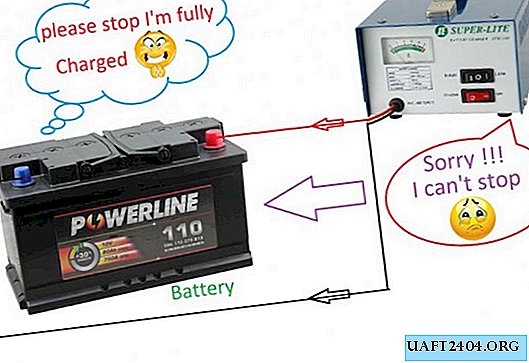
This device has absolutely no scarce parts. The whole circuit is built on just one transistor. It has LED indicators that indicate the status: is charging or the battery is charged.
Who needs this device?
Such a device is sure to be useful to motorists. Those who have a non-automatic charger. This device will make of your ordinary charger - a fully automatic charger. You no longer have to constantly monitor the charging of your battery. All you need to do is put the battery in charge, and it will turn off automatically only after it is fully charged.
Auto Charger Scheme

Here is the circuit of the automaton itself. In fact, this is a threshold relay that trips when a certain voltage is exceeded. The threshold is set by a variable resistor R2. For a fully charged car battery, it is usually equal to 14.4 V.
You can download the scheme here - //www.mediafire.com/file/0ldtxs4ma6mt2q2/12V-Auto-Cut-Off-Charger_circuit_By_hawkar_Fariq.pdf Source: //sdelaysam-svoimirukami.ru/?do=lastcomments
Printed circuit board

How to make a circuit board, you decide. It is not complicated and therefore you can easily throw it on a breadboard. Well, or you can get confused and do it on textolite with etching.
Customization
If all the details are serviceable, the configuration of the machine can be reduced only to setting the threshold voltage with resistor R2. To do this, we connect the circuit to the charger, but we do not connect the battery yet. We translate the resistor R2 to its lowest position according to the scheme. We set the output voltage on the charger to 14.4 V. Then we slowly rotate the variable resistor until the relay trips. Everything is configured.
Let's play with the voltage to make sure that the console works reliably at 14.4 V. After that, your automatic charger is ready to work.
Watch the video of the charger
In this video you can see in detail the process of the entire assembly, adjustment and testing in operation.
Original article in English
Share
Pin
Tweet
Send
Share
Send


